One key factor of reducing the costs of photovoltaic systems is to increase the reliability and the service life time of the PV modules. Today’s statistics show degradation rates of the rated power for crystalline silicon PV modules of 0.8%/year. To increase the reliability and the service life of PV modules one has to understand the challenges involved. For this reason, the international Task 13 expert team has summarized the literature as well as their knowledge and personal experiences on actual failures of PV modules.
The target audience of this work is PV module designers, PV industry, engineering lines, test equipment developers, testing companies, technological research laboratories, standardisation committees, as well as national and regional planning authorities.
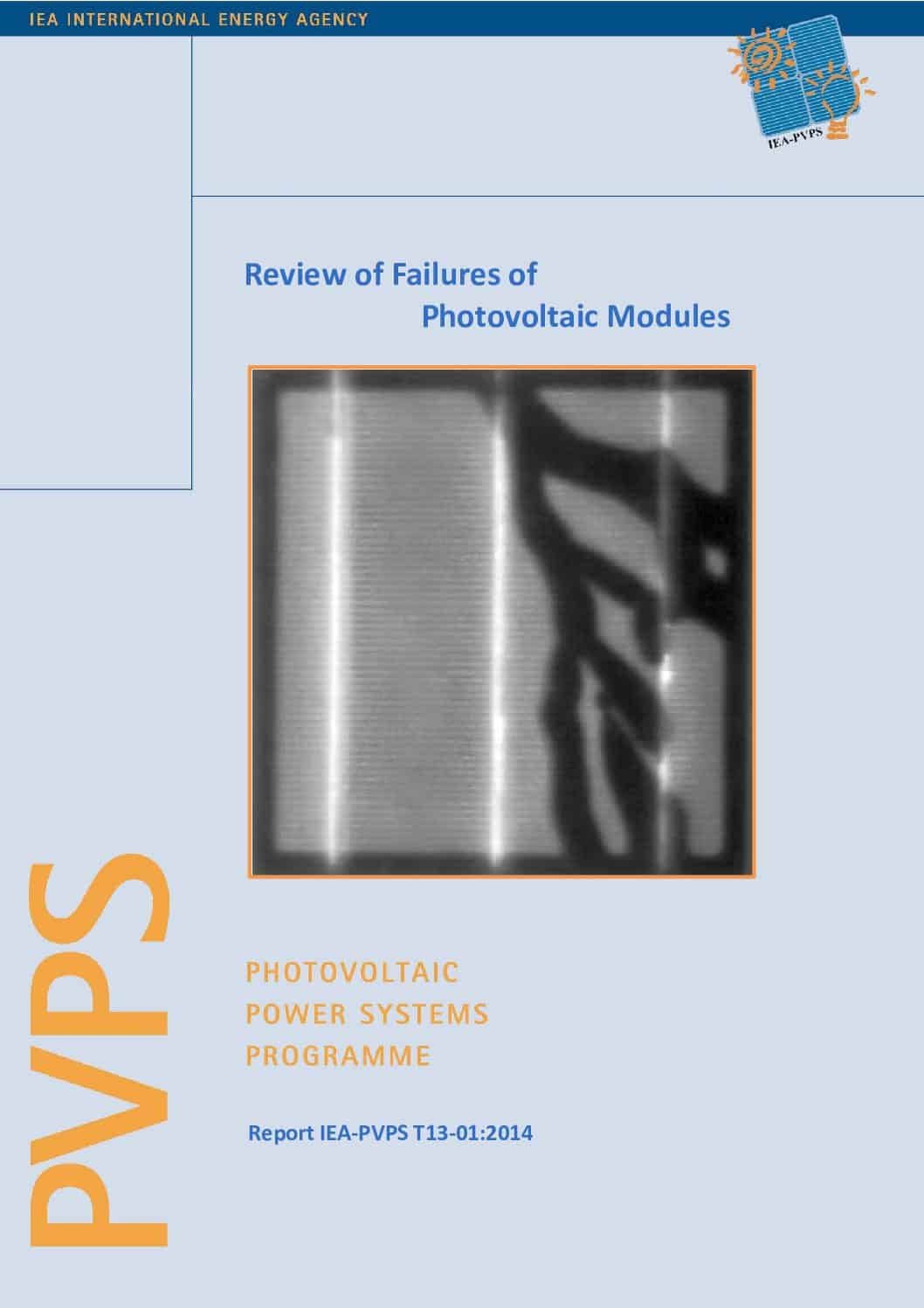
In the first part, this document reports on the measurement methods which allow the identification and analysis of PV module failures. Currently, a great number of methods are available to characterise PV module failures outdoors and in labs. As well as using I‑V characteristics as a diagnostic tool, we explain image based methods and visual inspection. For each method we explain the basis, indicate current best practice, and explain how to interpret the images. Three thermography methods are explained: thermography under steady state conditions, pulse thermography and lock-in thermography. The most commonly used of these methods is thermography under steady state conditions. Furthermore electroluminescence methods have become an increasingly popular standard lab approach for detecting failures in PV modules.
A less common but easier to use method is UV fluorescence. This method can be used to detect module failures similar to those detected with thermography and electroluminescence techniques; however, the PV modules must be sited outdoors for at least one and a half years for the method to be effective. For visual documentation of module conditions in the field, we set up a standard which is now accepted and used by all authors documenting such tests. This standard format allows the documentation of visible module failures in standardised way and makes the data accessible for statistical evaluation. Furthermore we introduce a signal transition method for the detection of defective circuits in installed PV modules. All methods are linked to the PV module failures which are able to be found with these methods.
In the second part, the most common failures of PV modules are described in detail. In particular these failures are: delamination, back sheet adhesion loss, junction box failure, frame breakage, EVA discolouration, cell cracks, snail tracks, burn marks, potential induced degradation, disconnected cell and string interconnect ribbons, defective bypass diodes; and special failures of thin-film modules, such as micro arcs at glued connectors, shunt hot spots, front glass breakage, and back contact degradation. Where possible, the origin of the failure is explained. A reference to the characterisation method is given to identify the failure. If available, statistics of the failure type in the field and from accelerating aging tests are shown. For each failure, a description of safety issues and the influence on the power loss is given, including typical follow-up failure modes.
In the third part, new test methods are proposed for detection of PV module failures in the field. A special focus is made on mechanical tests because many problems have arisen in the last few years from the mechanical loading of modules. These mechanical loads occur during transportation and from snow loads on modules mounted on an incline. Furthermore, testing for UV degradation of PV modules, ammonia corrosion (sometimes found in roofs of stock breeding buildings) and potential induced degradation are described. The latter method caused some controversy within the international standardization committee until the finalization of this report because many alternative suggestions from different countries were proposed. The test methods are explained in detail, linked to failure descriptions and the results are compared to real failure occurrences, where possible.